
Raspberry Pi ROS Robot Basic Operation Manual V1.0
1. The drive board and interface description

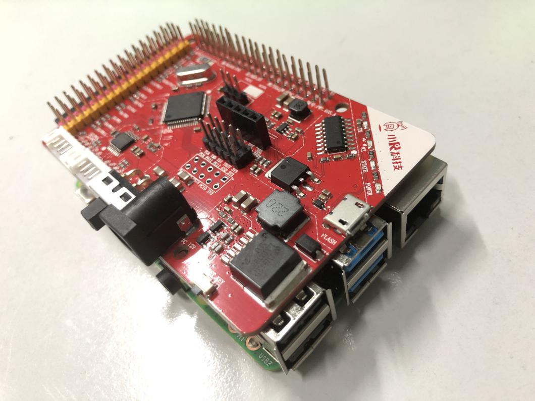
Raspberry Pi and Driver Board Combination

Raspberry Pi ROS robot overall circuit connection diagram

Overview of the PWR.ROS.A Radar Robot Drive Board Interface
PWR.ROS.A Robot Driver Board is a ROS Radar Car Robot Driver Board for Raspberry Pi 3B+/4B /Jetson Nano,Its main functions include:
1, regulator function: it can 7-12V DC input voltage buck to 5V or other voltage, used to power the main chip, or drive the motor and other external equipment.
2,Motor drive: The motor is driven by the motor drive chip to drive the motor forward, reverse, stop, accelerate and decelerate.
3, servo drive: the driver board with 8-way servo drive output interface, in the use of internal voltage to the servo power supply, can simultaneously drive 8 the maximum current does not exceed 100mA PWM servo.
4, the sensor drive: the driver board is not occupied by the GPIO are directly led to the bottom of the Raspberry Pi, and marked with yellow pins, each group of GPIO are 5V and GND power supply pins, marked in red and black.
5, sensor data acquisition: including motor speed, IMU gyroscope and other key data.
2、Basic user instructions
(When the robot is assembled) Connect the power supply to the power interface of the driver board, the specification of power supply is DC voltage 12-15V, with a current of at least 3A; power interface specifications of 5.5-2.1.
2.When the power switch is turned on, the LEDs on the driver board and Raspberry Pi light up, and the booting data can be seen on the display.

2.When the power switch is turned on, the LEDs on the driver board and Raspberry Pi light up, and the booting data can be seen on the display.
When the following XR-ROS HCI interface appears on the LCD, it indicates that it has been activated.

3.Introduction to the XR-ROS HCI system
The XR-ROS HCI system has three parts, which are the System state, the Operation process, and Additional functions. The corresponding functions are shown in the following table.
|
Attributes |
Functions |
Notes |
|
System state |
Detects the connection status of the radar, driver board and camera and displays the current network status. |
|
|
Operating procedure |
Include IMU calibration-->Build map-->Save map-->Navigation |
Without changing the environment in which the robot is operating, IMU calibration is theoretically only required once. |
|
Additional functions |
Terminate all processes and exit the interactive system |
|
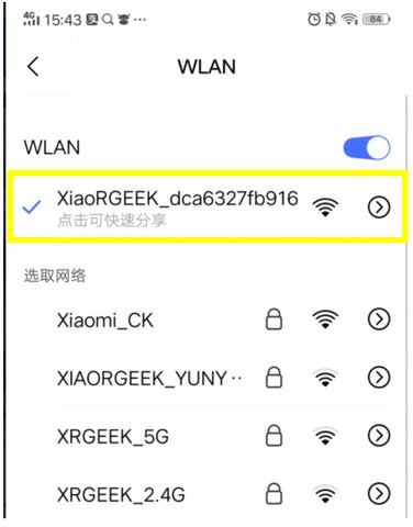
4.Turn on your phone's WLAN function, search for the surrounding WiFi signal, find the wireless signal starting with XiaoRGEEK and connect.
5.Adding robotic devices
Open the app when you are connected to the robot's wifi hotspot. When you launch the App for the first time, the App may request permission, please select "Agree". Then follow the App's instructions to add your robot. As shown in the picture below.
As a user, the only thing you need to change is the Master URI option, which is the IP address of the robot. This value is the "wifi IP" displayed in the system status of the XR-ROS HCI system. It is not recommended to change the parameters in Show more configurations, as they are the same as the ones shown in System Status. The firmware is matched, and once modified, the software will have uncontrollable errors. Show More Configurations The following figure shows.

6. IMU calibration
To calibrate the IMU (gyroscope system) when using the ROS robot for the first time, click the"IMU Calibration" button in the "Operating procedure" section of the XR-ROS HCI system, and wait for the robot to indicate that calibration is completed. IMU Calibration This is usually only needed once, and the calibration operation can be performed again when the robot is experiencing severe navigational deviations.

7.Build electronic maps
In unfamiliar environments, robots need to build electronic maps via lidar in order to provide reference data for subsequent navigation efforts.The created map will be saved in the robot system and if the map building operation is performed again, the new map will overwrite the old one. Of course, you can also save multiple maps at the same time through development by yourself
Click on the "make a map" button on the XR-ROS HCI system, and XR-ROS HCI system will prompt you with the message "Please complete the map on the App".

At this point the wifi icon in the Robot option on the APP will become active, as shown in the following image.

Click on the robot option, the APP enters the control page, and then select the upper left corner of the APP "click here to switch pages", select the "build map" option, the APP enters the build map state.

In the map building state, if your robot has a camera installed, you can see the video captured by the camera on the home screen, you can now use the joystick in the bottom left corner of the app to control the robot to walk through the current work site, in the top right corner of the app you can see the results of the radar scan of the robot and generate a map of the surrounding area, you can also click on the top right position to switch between the control interface and the video interface.
8 .Save map
After the robot acquires the map data in the map building state, it needs to save it, and our robot has two ways to save the map.
①.In the "Create Map" screen, tap the red dot at the bottom right corner to display "Refresh Map" and "Save Map" options, select "Save Map".
②.Click the "Save Map" button on the "Operating procedure" page of the XR-ROS HCI system.

Note: The save map function on the APP only effected in map building mode.
9.Autonomous navigation
After building a map of a specific location, you can experience the navigation effect.
Click on the "Navigation" button on the XR-ROS HCI system and then switch to the "Navigation" option on the APP UI.

①、Firstly, set the start point according to the current position of the robot, in the "Navigation" interface, select the "Set Start Point" option in the lower left corner, then press and hold in the map, and then drag your finger to the general direction of the robot's nose, a blue arrow cursor will appear on the app, the direction of the arrow is the direction of the robot's nose, the start point doesn't have to be very precise, but the more precise the start point is, the faster the robot will enter the autonomous navigation state.

In the "Navigation" interface, select the "Set Navigation Point" option in the lower left corner, and then in the APP display. On the map, select the destination you want the robot to reach and press and hold it, then press and hold it towards the front of the car when you want the robot to reach the destination. Drag your finger and a blue arrow cursor will appear on the APP, the arrow points in the direction of the robot's front end when it reaches its destination. Adjust the direction, release the finger and the robot will automatically map out the path to its destination and execute it.If it encounters an unexpected obstacle midway through the journey, the robot will reroute a new route around it.

3. Getting start for development
1.Commonly used development tools
Putty: Used to remotely log in to the Raspberry Pi system via SSH to execute commands.
Winscp: used to remotely connect to the Raspberry Pi system to transfer files.
SDFormatter: used to format the TF card before burning the image to TF card.
Win32DiskImager: used to burn the system image to TF card, or read the whole image from TF card to backup.
2.Burning system image
Note: If you are using the TF card that comes with the product, then there is a robot system image built into the TF card, if you are using your own blank TF card, Or if there is a problem with the original image, then you need to flush the robot system image to the TF card again. The system image burn tutorial is as follows.
①.Insert the TF card into the card reader, and then insert the card reader into the USB port of the computer, at this time you can see on the computer has been recognized as a USB storage device TF card.
②.Use SDFormatter to format the TF card.
③.Use Win32DiskImager to write the robot system image to TF card.
3.System architecture