
Take you into the WIFI robot car - to understand the basic principles
WIFI robot car is the childhood dream of many people, my desire for WIFI robot car comes from the video remote control car in the "Kid's Home", at that time I thought it would be great if one day I can make my own wifi robot car. Until now, I have realized my childhood dream and I made many robot cars of my own.But what if most beginners, who are not electronics majors or computer majors, are interested in WIFI/Bluetooth-controlled smart robot cars? It's true that for a person with the wrong profession, it's compartmentalized, but it doesn't matter, firstly, let me tell you something about the principles of the robot car.
Given that the Bluetooth Smart Car and the WIFI Smart robot car are actually very similar, but with the WIFI module replaced by a Bluetooth module, the Bluetooth Car will not be elaborated on in detail.
The WIFI smart robot car of ours uses a router + PC or mobile phone or web control method. Its basic principle is divided into 4 major blocks:
1, make an ordinary wireless router a small computer running Linux by brushing it into the open-source OpenWrt system.
What is OpenWRT? 1. About OpenWrt When Linksys released the source code of WRT54G/GS, there were many different versions of Firmware on the Internet to enhance the original functionality. The first is that it is difficult to combine the strengths of each version of Firmware, and the second is that this version is further and further away from the official Linux distribution. OpenWrt chose a different path, it started from scratch, adding software bit by bit, making it closer to the Linksys version of Firmware. Development speed.
In a nutshell, it's a retrofit from Cisco's routing source code, a small Linux system for routers with certain chips, with this system, our routing is no longer as simple as surfing the Internet, we can install various programs and drivers on it, using routing as a platform, users are free to load USB cameras, network cards, sound cards, and so on.
We have a program running on our WIFI board, called mjpg-streamer, which encodes the video from the USB camera and returns it to the host computer via WIFI, so we can see the video from the robot car.
At the same time, the routing usually has a TTL serial port reserved, the TTL serial port is used for debugging or brushing, we bring out this TTL serial port, and then through the Ser2net software installed inside the routing, we can transfer the commands from the WIFI channel to the serial port output, and the role of the serial port here is to communicate with the microcontroller chip MCU so that the microcontroller knows what action the user wants him to do.
Robot car WIFI (routing) module:

2、Single-chip system and downstream computer
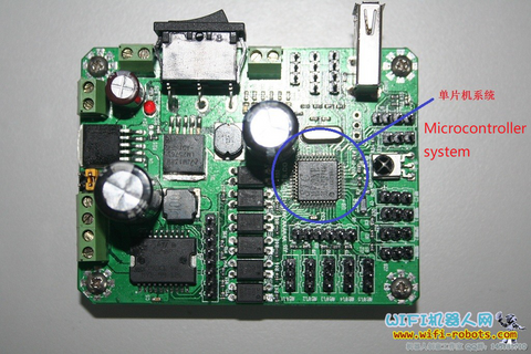
Microcontroller system is also the simplest small computer system, but its frequency is very low, not suitable for big data, its main function is to control the level of its output pins (IO port), so that the motor driver chip to drive the motor forward or reverse, to achieve the robot forward and backward.
We call the program running inside the microcontroller system as the lower unit, the role of this program is to receive instructions from the upper unit, and decode and analyze to understand what kind of action the user sends, and then let the microcontroller chip's designated pins for high and low-level assignment, of course, the upper sending unit of this instruction is the WIFI module, which is the routing, and then the upper level is the PC / mobile phone and other control terminals, which is the upper unit.
This is the first time I've ever seen a PC or microcontroller with a TTL serial port, and I've never seen a PC or microcontroller with a TTL serial port.
In addition to the TTL serial port, there is a serial port called RS232 level, also known as 9-pin serial port, that is, the serial port behind the ordinary desktop computer, the level of this serial port is not TTL, so the debugging can not directly use this serial port and our various modules to communicate, we must buy 232 to TTL level board.
Robot car Microcontroller (MCU) systems:
3、Motor drive circuit
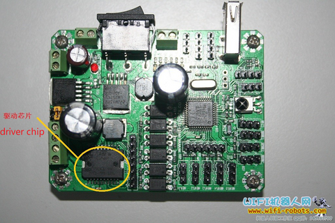
As I said above, the microcontroller can parse the instructions sent by the upper computer, by judging the instructions, and then let itself a pin level to pull up or down, but the microcontroller's pin output current is very small, you can make him light LED lights, but drive our large body is impossible, so you need a driver chip to drive the motor operation, that is, the microcontroller with the pin level of the way to tell the driver module, for example, the microcontroller's pin P10-P13 is 1010, the driver module will output two forward voltage, the car forward, if it is 0101, the car backed up.
Robot car Drive Circuit Module:
4、Uploader
The upper computer is the part that sends the commands, we send the commands to the WIFI module/router through the upper computer, then through the router's conversion, the commands are forwarded to the microcontroller so that the robot executes our commands, at the same time the upper computer sends a video request to the router, the video processor on the routing side sends the acquired USB camera video back to the upper computer, the upper computer decodes it and displays it.
The upper computer is actually written to send data to the routing side with a socket connection via TCP/UDP and other communication methods, where our upper computer is Client mode and the routing side is server mode, which has the advantage that it doesn't require any forwarding operation, and we can directly connect to the WIFI smart trolley robot to manipulate it.
Okay, to summarize: the whole smart robot car works that are shown as below:

Finally, please find the website:www.xiaorgeek.com of robot car for reference