
Description of WIFI/Bluetooth Smart Car Robot Driver Board
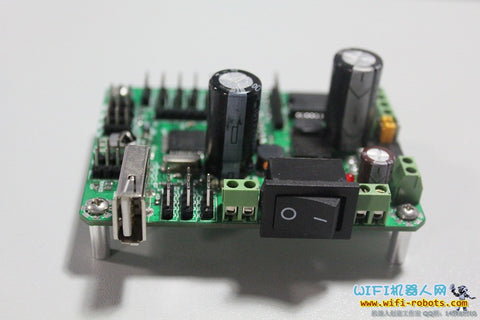
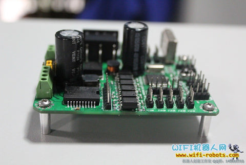
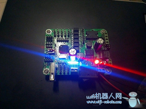
The photo of driver board:
Compared with a fountain pen, very mini: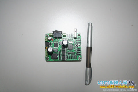
Photo of running with 12V lithium battery:
(Green version)
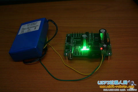
(Blue version)
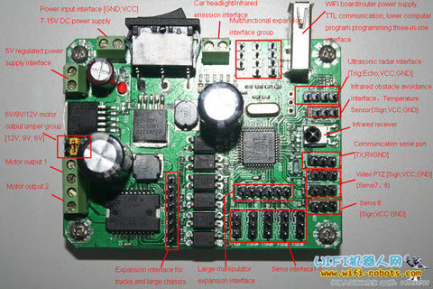
Interface description diagram:
Driver board hardware resource characteristics:
- MCU processor
--STC11F32XE, 32K Flash, 1280 bytes SRAM, on board crystal oscillator 22.1184MHz, compared with traditional 51 single-chip microcomputer,it has the following characteristics:
1) Low power consumption, strong anti-interference, and super encryption;
2) Support 1T mode, 22.1184MHz main frequency is approximately equivalent to 265MHz of traditional single-chip microcomputer;
3) Support IAP technology, 29K EEPROM space can be used to save user data;
4) It has an independent baud rate generator.
- Motor drive chip
--L298, built-in dual full bridge drive circuit, can drive 2 DC motors, can also drive two-phase stepper motors, standard 2A drive current, new imported SMT package, performance is much better than domestic plug-in package L298, the price is also Much more expensive.
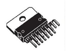
Domestic plug-in package L298
- Dual power supply voltage regulation
This driver board comes with a dual-channel voltage stabilization system, which can stabilize the 7-16V DC power input to 5V and other voltages for use by the robot's external equipment. Compared with other driver boards and Arduino driver boards, these driver boards are not stable. For the pressure system, the user needs to lower the pressure input by himself, which is very troublesome.
--2 pieces of LM2596, respectively supporting 3A current drive output, brand new imported chips, low heat, performance and price are much higher than domestic chips
- Interface resources and characteristics
1) 1 motor output interface, standard configuration to drive 2 DC motors (4 channels of low current motors can also be driven in parallel), and optional stepper motors
2) 1 motor expansion logic control interface, used to control an external high-power motor chassis (such as a big-foot motor);
3) 5 steering gear drive interfaces (can be expanded to 8 channels);
4) 1 servo extended logic control interface group, used to control the external super-power servo;
5) 3 infrared obstacle avoidance interfaces;
6) 1 TTL pin header serial port;
7) One infrared integrated receiver;
8) 4 reserved interfaces, which can be connected to temperature sensor, ultrasonic module, FM module with I2C interface, etc.;
9) 1 USB interface, perfectly adapted to wireless routers such as 703, integrates 5V power supply and TTL serial port, and can also be connected to an external serial port module, such as a fingerprint module, etc.;
10) 1 drive interface with a maximum output of 500mA, which can be connected to infrared transmitter, buzzer, strong light diode, relay, etc.;
11) 1 power switch, 8A working current, super reliability;
12) 1 DC power input interface, 7-15V range input;
13) 1 5V voltage output interface, standard 1A current;
14) Motor drive voltage selection jumper switch, optional 6V/9V/12V output.
15) 6 groups of bright LED running indicators.
16) The key logic parts are isolated by optocouplers, which greatly improves the stability.
17) You can use the STC-ISP download program to program online.
Special statement: There are pins marked VCC GND PWM on the back of the driver board. Please be sure to recognize and connect the wiring. In addition, the voltage input, TTL level and other parameters must be marked in accordance with the driver board icon.